In this post, we will talk about the fault detection cases of the main shaft bearing faults of wind turbines.
Main Shaft Bearing
Main shaft bearings are considered one of the most critical equipment of wind turbines. These enormous bearings sit in the nacelle at the top of the turbine tower. Wind-turbine designs commonly use spherical-roller bearings (SRB) units that are more than 1 meter in diameter, and tapered roller bearings (TRB) are also used. Designers often select single SRB designs, one supported by a single main bearing and two torque arms that carry gearbox reaction loads. Their primary function is to support the weight of the rotor, along with the other loads generated by the wind. They allow the main shaft to spin smoothly and transmit torque to the adjacent equipment (gearbox).
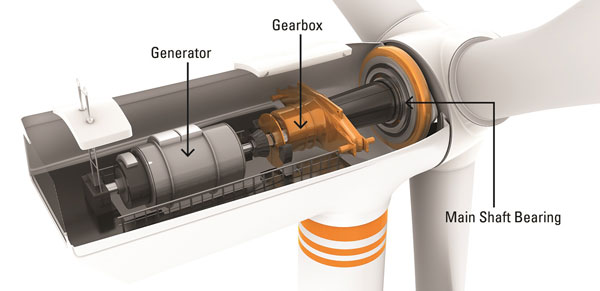
Main shaft bearings rotate at lower speeds, around 10 rounds per minute (RPM); however, they are operated under challenging conditions such as variable loads created by air flow fluctuations. Two factors are generally considered to contribute to early failures in main shaft bearings:
- High thrust load
- Inadequate lubricant film generation
The unplanned replacement of a main-shaft bearing can cost operators up to $450K and have an obvious impact on financial performance. Main shaft bearing failures may also lead to gearbox damage due to excessive thrust.
Case Studies
Considering the costs and secondary effects, monitoring these bearings and taking appropriate actions before a failure occurs is crucial. And using a large number of farm/turbine data with smart machine learning techniques enables you to take proactive measures. Let’s start with a case study in which data & algorithms help detect main shaft bearing faults.
Case Study 1
The figure below shows the main shaft bearing temperature signal (dark blue) against the control boundaries obtained from the learned behavior (light blue) from its historical data. Also, a deviation plot is added under the signal plot to emphasize the deviations from its normal behavior for fault-free and faulty regions.
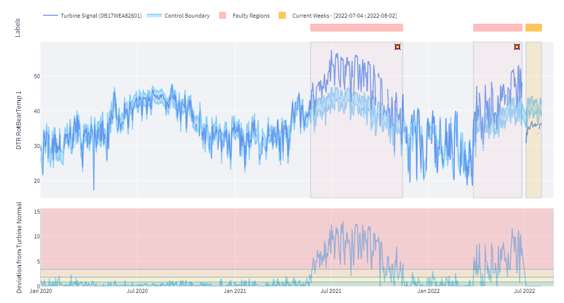
The figure above depicts two and a half years of operation for the specific turbine. Rather than using simple industry standard thresholds for the signals, we used a smart way to determine whether the signal is within the “normal” operating range. To do that, we employed a decision tree-based machine learning algorithm to learn the normal behavior from its historical data. Both exogenous (operational data such as wind speed, ambient temperature, rotational speeds etc.) and auto-regressive inputs are taken into account in the machine learning model. Machine learning model outputs are coupled with a control chart mechanism. Control charts are commonly used in the industry for monitoring statistical processes. If a signal deviates from the boundaries for a certain period, it is considered that the equipment exhibits anomalous behavior.
As we can see in the deviation plot, turbine normal behavior (green zone) stays in the 1 to 3 degree Celsius range during the fault-free period (Jan 2020 - June 2021). However, when it nears the faulty ranges (June 2021 and April 2022), deviation from turbine normal dramatically escalates up to 12 degrees. These escalations are taken as fault indicators and fault flags are raised automatically after consistency checks. Consistency checks are essential to deal with false alarms. Otherwise, the excessive amount of alarms may overburden farm personnel.
Another measure we use for fault detection is comparing turbine signals among turbines of the same type on the same farm. To do that, we determine the seasonal central tendency behavior of the same type of turbines on the same farm and see how the turbine signal deviates from the fleet.
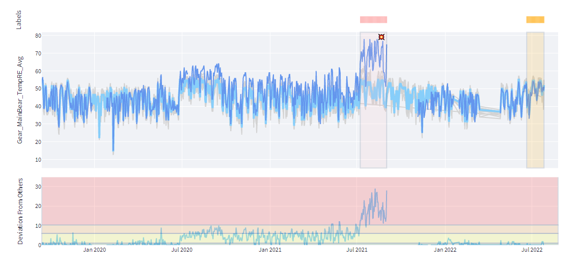
The figure below shows the turbine signal (dark blue) against the turbine signals (gray) and their central tendency with seasonal effects (light blue). Also, a deviation plot is added under the main plot to emphasize the differences. Region thresholds in the deviation plot are determined by the deviations in the fault-free periods of the specific turbine. Aside from the fault regions, one can see that the main bearing temperature differences stay below 1 degree Celsius. Deviations from seasonal farm behavior tend to increase as it nears the faulty regions.
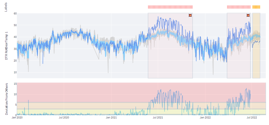
Kavaken algorithms can raise flags at the beginning of these two faulty regions. The first fault region ended with a repair action of the main bearing shaft, and the bearing was replaced at the end of the second one. As can be seen from the current week's signals, temperature values came back to normal operating conditions.
Case Study 2
Let’s move to another case from another IPP with a different OEM turbine and type. Similar to the first case, as seen in the main shaft bearing temperature graph below, it exceeded the control chart boundaries (turbine’s learned normal behavior from its historical trends) at the beginning of July 2021, which triggered the fault alarm raise. The next indicator was to check whether this turbine differs significantly from the reference turbine’s seasonal central tendency on the same farm.
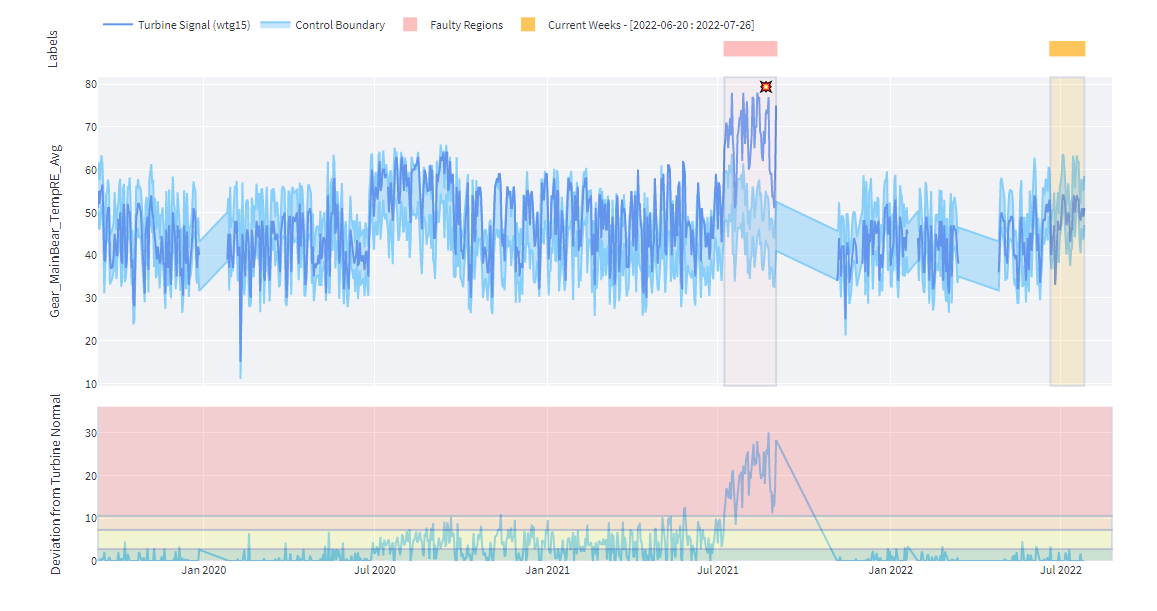
As we see in the graph below, the turbine signal significantly deviates from the fleet, leading to the rise of the fault alarm. Farm personnel confirmed the alarm and the bearing was replaced afterward.
Conclusion
These are good examples of how an intelligent early warning system that uses big data and machine learning algorithms can help farm personnel make smarter decisions within a predictive maintenance program. It allows farm personnel to be prepared for repair/replacement tasks months before the situation becomes serious.
As mentioned in the introduction, detecting and diagnosing main shaft bearing faults early is of paramount importance. Otherwise, the replacement and operational costs associated with the main shaft bearing fault as well as the secondary damages cause undesired outcomes.
This brings us to the end of the post. Stay tuned for new case studies!


